
The most convenient sample measurements with MultiSample™ scan
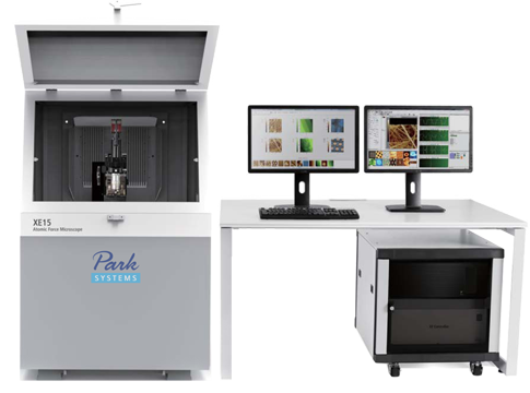
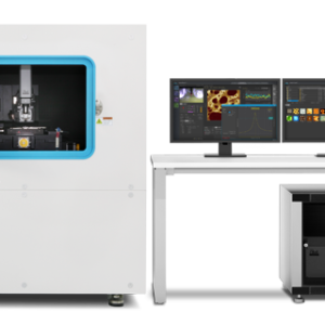
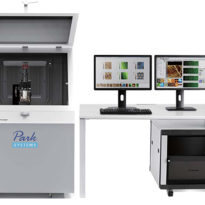
Park XE15 MultiSample™ scan system
- Automated imaging of multiple samples in one pass
- Specially designed multi-sample chuck for the loading of up to 16 individual samples
- Fully motorized XY sample stage travels up to 150 mm x 150 mm
Using the motorized sample stage, MultiSample Scan™ enables programmable multiple region imaging in step-and-scan automation.
Here’s how it works:
1. Register multiple scan positions defined by a user
2. Image from the first scan position
3. Lift a cantilever
4. Move the motorized stage to the next user-defined coordinate
5. Approach
6. Repeat scan
The registration of multiple scan positions are easily carried out by either entering sample-stage coordinates or sample de-skewing by two reference points. This automated feature greatly increases productivity by reducing the need for your interaction during the scan process.
Accurate XY Scan by Crosstalk Elimination
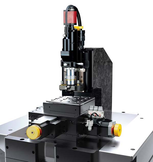
Park Systems’ advanced Crosstalk Elimination (XE) scan system effectively addresses all of the above-mentioned problems. In this configuration, we used a 2-dimensional flexure stage to scan the sample in only the XY direction, and a stacked piezoelectric actuator to scan the probe cantilever in the Z direction only. The flexure stage used for the XY scanner is made of solid aluminum. It demonstrates high orthogonality and an excellent out-of-plane motion profile. The flexure stage can scan large samples (~1 kg) up to a few 100 Hz in the XY direction. This scan speed is sufficient because the bandwidth requirement for the XY axes is much lower than that for the Z axis. The stacked piezoelectric actuator for the Z-scanner has a high resonance frequency (~10 kHz) with a high push-pull force when appropriately pre-loaded.
XE scan system
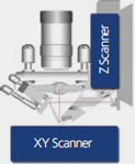
- independent, loop XY and Z flexure scanners for sample and probe tip
XY flexure scanner
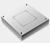
- Flat and orthogonal XY scan with low residual bow
XE-Peformence
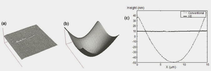 Figure 9. Zero background curvature by Park Systems XE-system (a) and typical background curvature of a conventional AFM system with a tube scanner (b). (c) shows the cross-section of these background curvatures.
Figure 9. shows unprocessed AFM images of a bare silicon wafer taken with the XE-system (a), and with a conventional AFM (b). Since the silicon wafer is atomically flat, most of the curvatures in the image are scanner-induced artifacts. Figure 9. (c) shows the cross-section of the images in Figure 9. (a) and (b). Since the tube scanner has intrinsic background curvatures, the maximum out-of-plane motion is as much as 80 nm when the X-axis moves 15 μm. The XE scan system has less than 1nm of out-of-plane motion for the same scan range. Another advantage of the XE scan system is its Z-servo response. Figure 10. is an image of a porous polymer sphere (Styrene Divinyl Benzene), whose diameter is about 5 µm, taken with the XE-system in Non-Contact mode. Since the Z-servo response of the XE-system is very accurate, the probe can precisely follow the steep curvature of the polymer sphere as well as small porous surface structures without crashing or sticking to the surface. Figure 11. shows another example that demonstrates the high performance of the z-servo response with a flat background.
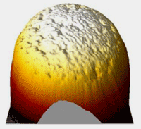
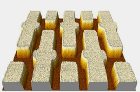
Figure 10. Figure 11.
Better tip life, sample preservation, and accuracy with True Non-Contact™ Mode
In True Non-Contact™ Mode, the tip-sample distance is successfully maintained at a few nanometers in the net attractive regime of inter-atomic force. The small amplitude of tip oscillation minimizes the tip-sample interaction, resulting in superb tip preservation and negligible sample modification.
True Non-Contact™ Mode
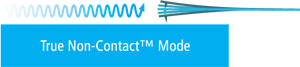
- Less tip wear = Prolonged high-resolution scan
- Non-destructive tip-sample interaction = Minimized sample modification
- Immunity from parameter-dependent results
Tapping Imaging
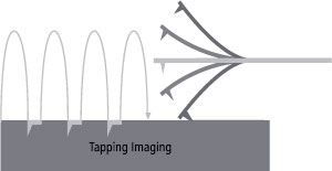
- Quick tip wear = Blurred low-resolution scan
- Destructive tip-sample interaction = Sample damage and modification
- Highly parameter-dependent
Longer Tip Life and Less Sample Damage
The sharp end of an AFM tip is so brittle that once it touches a sample, it becomes instantly blunt and limits the resolution of an AFM, and reduces the quality of the image. For softer samples, the tip will damage the sample and also result in inaccuracies of sample height measurements. Consequently, preserving tip integrity enables consistent high resolution and accurate data. True Non-Contact Mode of the XE-AFM superbly preserves the tip, resulting in much longer tip life and less sample damage the figure, displayed in 1:1 aspect ratio, shows the unprocessed raw data image of a shallow trench isolation sample imaged by the XE-AFM, whose depth is also confirmed by scanning electron microscope (SEM). The same tip used in the imaging of the sample shows no tip wear even after taking 20 images. 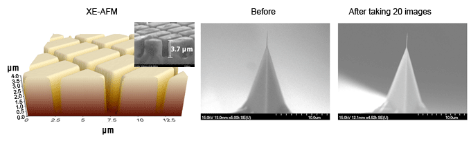
he Most Extensible AFM Solution
Supports Park’s most extensive range of SPM modes and options in the industry
Today’s researchers need to characterize a wide range of physical properties under diverse measurement conditions and sample environments. Park Systems provides the most extensive range of SPM modes, the largest number of AFM options, and the best option compatibility and upgradeability in the industry for advanced sample characterization.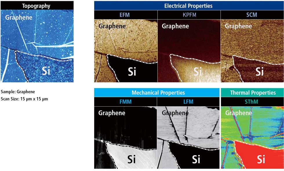
Park XE15 has the most Extensive range of SPM modes (*Optionally available)
Standard Imaging
- True Non-Contact AFM
- Basic Contact AFM
- Lateral Force Microscopy (LFM)
- Phase Imaging
Chemical Properties*
- Chemical Force Microscopy
- Electrochemical Microscopy (EC-AFM)
Force Measurement*
- Force Distance (FD) Spectroscopy
- Force Volume Imaging
Electrical Properties*
- Conductive AFM
- I-V Spectroscopy
- Kelvin Probe Force Microscopy (KPFM)
- Scanning Capacitance Microscopy (SCM)
- Scanning Spreading-Resistance Microscopy (SSRM)
- Scanning Tunneling Microscopy (STM)
- Time-Resolved Photo Current Mapping (PCM)
Magnetic Properties*
- Magnetic Force Microscopy (MFM)
Dielectric/Piezoelectric Properties*
- Electrostatic Force Microscopy (EFM)
- Dynamic Contact EFM (EFM-DC)
- Piezoelectric Force Microscopy (PFM)
Mechanical Properties*
- Force Modulation Microscopy (FMM)
- Nanoindentation
- Nanolithography
Thermal Properties*
- Scanning Thermal Microscopy (SThM)
Brochures: park_xe15
Park XE15 Specifications
XY Scanner
Single-module flexure XY scanner with closed-loop control Scan range : 100 µm × 100 µm
Motorized Stage
XY travel range : 150 mm × 150 mm, motorized Z travel range : 25 mm Focus travel range : 20 mm, motorized Optional precision encoders for repeatable XY positioning
Z Scanner
Guided high-force Z scanner Scan range : 12 µm 25 µm (optional)
Sample Mount
Sample size : Up to 150 mm Thickness : Up to 20 mm
Vision
Direct on-axis vision of sample surface and cantilever Coupled with 10× objective lens (20× optional) Field-of-view: 480 × 360 µm CCD: 1 Mpixel
Software
XEP
Dedicated system control and data acquisition software Adjusting feedback parameters in real-time Script-level control through external programs(optional)
XEI
AFM data analysis software (running on Windows, macOS X, and Linux)
Electronics
High performance DSP : 600 MHz with 4800 MIPS Maximum 16 data images Maximum data size : 4096 × 4096 pixels Signal inputs : 20 channels of 16 bit ADC at 500 kHz samplings Signal outputs : 21 channels of 16 bit DAC at 500 kHz settling Synchronous signal : End-of-image, end-of-line, and end-of-pixel TTL signals Active Q control (optional) Cantilever spring constant calibration (optional) CE Compliant Power: 120 W Signal Access Module (Optional)
AFM Modes (*Optionally available)
Standard Imaging
True Non-Contact AFM Basic Contact AFM Lateral Force Microscopy (LFM) Phase Imaging Intermittent (tapping) AFM
Force Measurement*
Force Distance (FD) Spectroscopy Force Volume Imaging
Dielectric/Piezoelectric Properties*
Electric Force Microscopy (EFM) Dynamic Contact EFM (EFM-DC) Piezoelectric Force Microscopy (PFM) PFM with High Voltage
Mechanical Properties*
Force Modulation Microscopy (FMM) Nanoindentation Nanolithography Nanolithography with High Voltage Nanomanipulation Piezoelectric Force Microscopy (PFM)
Magnetic Properties*
Magnetic Force Microscopy (MFM)
Electrical Properties*
Conductive AFM IV Spectroscopy Kelvin Probe Force Microscopy (KPFM) KPFM with High Voltage Scanning Capacitance Microscopy (SCM) Scanning Spreading-Resistance Microscopy (SSRM) Scanning Tunneling Microscopy (STM) Time-Resolved Photo Current Mapping (PCM)
Chemical Properties*
Chemical Force Microscopy with Functionalized Tip Electrochemical Microscopy (EC-AFM)
AFM Options
Active Temperature-controlled Acoustic Enclosure
Innovative control brings the system quickly to its temperature equilibrium Temperature stability of less than 0.05 ºC within10 minutes of closing AE door Includes an active vibration isolation system
Encoders for Motorized Stage
The encoded XY stage travels in 1 µm resolution with 2 µm repeatability The encoded Z stage travels in 0.1 µm resolution with 1 µm repeatability
Sample Plates
Vacuum grooves to hold wafers Sample dimension: Up to 150 mm
25 µm Z-scanner Head
Z scan range: 25 µm Resonant frequency: 1.7 kHz Laser type: LD (650 nm) or SLD (830 nm) Noise floor : 0.03 nm (typical), 0.05 nm (maximum)
XE Optical Head
Optical access: top and side Z scan range: 12 µm or 25 µm Laser type : LD (650 µm) or SLD (830 µm) Noise floor : 0.03 nm (typical), 0.05 nm (maximum) Resonant frequency : 3 kHz (12 µm XE Head), 1.7 kHz (25 µm XE Head)
Clip-type Probehand
Unmounted cantilever can be used Tip bias range : -10 V to + 10 V Tip bias function available for EFM and Conductive AFM Support all the standard and advanced modes but STM, SCM, and in-liquid imaging
Signal Access Module (SAM)
Enables access to various input/output signals for AFM Scanner driving signal for the XY and Z scanners Position signal for the XY and Z scanners Cantilever deflection signals of the vertical/lateral direction Bias signal for the sample and the cantilever Driving signal for XE15 Auxiliary input signal to the system
Accessories
Electrochemistry Cell Universal Liquid Cell with Temperature Control Sample Stages with Temperature Control Magnetic Field Generator
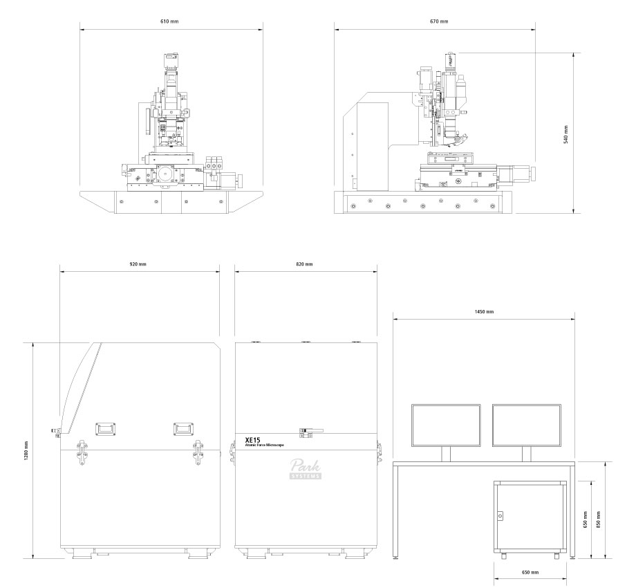
Dimensions in mm
Reviews
There are no reviews yet.